Unified Modelling Language (UML) Diagrams: Designing Use Case, Sequence, and Class Diagrams to Visualise System Interactions and Logical Data Flow
Unified Modelling Language (UML) diagrams are widely used in software and business analysis to represent systems in a clear visual format. They help teams understand how users interact with a system, how processes move step by step, and how data objects relate to each other. Instead of relying only on written requirements, UML adds structure and clarity through visual models.
For business analysts, UML diagrams are especially useful during requirement gathering, process mapping, and solution discussions with technical teams. A well-made diagram reduces confusion, improves communication, and supports better design decisions. Learners in a business analysis course in pune often study UML because it connects business requirements with technical implementation in a practical way.
This article explains three commonly used UML diagrams: Use Case diagrams, Sequence diagrams, and Class diagrams. It also covers when to use each one and how they support system understanding and logical data flow.
Why UML Diagrams Matter in System Design
UML is not only for developers. It is a shared language that supports communication across stakeholders, including clients, business analysts, project managers, testers, and engineers. Each diagram type serves a different purpose, and together they provide a more complete view of the system.
The main benefits of UML diagrams include:
Better Requirement Clarity
Visual representations help teams identify missing requirements, duplicate steps, or incorrect assumptions early in the project.
Improved Stakeholder Communication
Non-technical stakeholders may find diagrams easier to understand than long technical documents. This leads to faster discussions and better alignment.
Support for Logical Data Flow and Interaction Mapping
UML diagrams help trace how an action starts, which system components respond, and how data moves between objects or modules.
Use Case Diagrams: Understanding User Goals and System Scope
A Use Case diagram shows what users want to do with a system and how the system supports those actions. It focuses on user goals rather than technical details. This makes it very useful during the early requirement analysis phase.
Main Components of a Use Case Diagram
- Actors: External users or systems interacting with the application
- Use Cases: Functions or goals performed in the system
- System Boundary: The defined scope of the system
- Relationships: Associations between actors and use cases
Example Scenario
Consider an e-commerce platform. Actors may include Customer, Admin, and Payment Gateway. Use cases may include Register, Place Order, Track Order, and Process Refund. This diagram helps stakeholders understand what features are included and who uses them.
Best Practices
- Keep use cases action-oriented, such as “Submit Application” or “Generate Report”
- Avoid technical implementation details
- Use simple labels that stakeholders can understand
- Define system boundaries clearly to prevent scope confusion
Use Case diagrams are ideal when teams need a high-level view of functionality before moving to detailed design.
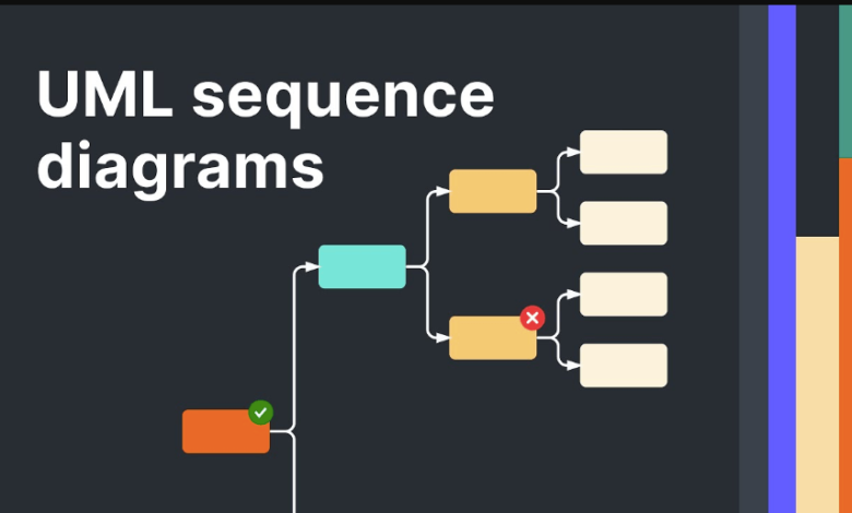
Sequence Diagrams: Mapping the Flow of Interactions Over Time
A Sequence diagram shows how different actors and system components interact in a specific order to complete a process. It is particularly useful for understanding transaction flows, API calls, validations, and system responses.
What a Sequence Diagram Includes
- Actors or Objects involved in the interaction
- Lifelines representing each participant over time
- Messages showing calls, responses, and data exchange
- Activation bars indicate when an object is performing an action
Example Scenario
In a login process, the user enters credentials, the application sends data to an authentication service, the service verifies the details in the database, and the system returns a success or error message. A Sequence diagram captures this order step by step.
Why It Is Important
Sequence diagrams help teams:
- Validate process logic
- Identify unnecessary steps
- Detect integration gaps
- Clarify dependencies between components
They are especially useful in agile projects where teams build features in iterations and need precise interaction flows for development and testing.
See also: Media Authority Techtrends Bouncemediagroup Strategy
Class Diagrams: Structuring Data and Relationships
A Class diagram represents the static structure of a system. It shows classes, their attributes, methods, and the relationships between them. While Use Case and Sequence diagrams focus on behaviour, Class diagrams focus on the data model and object relationships.
Core Elements in a Class Diagram
- Class Name
- Attributes (data stored in the class)
- Methods (functions performed by the class)
- Relationships such as association, inheritance, and aggregation
Example Scenario
In a student management system, classes may include Student, Course, Instructor, and Enrollment. The diagram can show that a Student can enrol in multiple Courses, and each Course may have one Instructor. This supports logical data flow by defining how entities connect.
Practical Value for Analysts
Business analysts may not create deeply technical Class diagrams in every project, but understanding them helps in:
- Discussing data requirements with developers
- Validating entity relationships
- Supporting database and application design conversations
This is one reason UML remains an important topic in a business analysis course in pune, where learners are expected to bridge business needs and system design logic.
How to Choose the Right UML Diagram for the Task
Choosing the right diagram depends on the question the team is trying to answer.
Use Case Diagram for Functional Scope
Use this when the team needs to understand who interacts with the system and what major functions are required.
Sequence Diagram for Process Flow
Use this when the team needs to understand how interactions happen step by step during a specific transaction or scenario.
Class Diagram for Data Structure
Use this when the team needs to define entities, relationships, and the application’s static structure.
In many projects, all three are used together. A Use Case diagram defines the feature, a Sequence diagram explains the interaction flow, and a Class diagram supports the data model.
Conclusion
UML diagrams are practical tools for visualising system behaviour and structure. Use Case diagrams help define user goals and system scope. Sequence diagrams illustrate the flow of interactions over time. Class diagrams map the static data structure and relationships. When used correctly, these diagrams improve communication, reduce errors in requirements, and support better design outcomes.
For business analysts, learning UML is not about drawing complex diagrams for every project. It is about selecting the right visual model to explain requirements clearly and connect business intent with technical execution.